Router Password Recovery Procedure
To recover a router password, do the following:
Prepare the Device
Step 1. Connect to the console port.
Step
2. If you have lost the enable password, you would still have access to
user EXEC mode. Type show version at the prompt, and record the
configuration register setting.
R>#show version
<show command output omitted>
Configuration register is 0x2102
R1>
The
configuration register is usually set to 0x2102 or 0x102. If you can no
longer access the router (because of a lost login or TACACS password),
you can safely assume that your configuration register is set to 0x2102.
Step 3. Use the power switch to turn off the router, and then turn the router back on.
Step 4. Press Break on the terminal keyboard within 60 seconds of power up to put the router into ROMmon.
Step
5. Type confreg 0x2142 at the rommon 1> prompt. This causes the
router to bypass the startup configuration where the forgotten enable
password is stored.
Step 6. Type reset at the rommon 2> prompt. The router reboots, but ignores the saved configuration.
Step 7. Type no after each setup question, or press Ctrl-C to skip the initial setup procedure.
Step 8. Type enable at the Router> prompt. This puts you into enable mode, and you should be able to see the Router# prompt.
Step
9. Type copy startup-config running-config to copy the NVRAM into
memory. Be careful! Do not type copy running-config startup-config or
you will erase your startup configuration.
Step 10. Type show
running-config. In this configuration, the shutdown command appears
under all interfaces because all the interfaces are currently shut down.
Most importantly though, you can now see the passwords (enable
password, enable secret, vty, console passwords) either in encrypted or
unencrypted format. You can reuse unencrypted passwords. You must change
encrypted passwords to a new password.
Step 11. Type configure terminal. The hostname(config)# prompt appears.
Step 12. Type enable secretpassword to change the enable secret password. For example:
R1(config)# enable secret cisco
Step
13. Issue the no shutdown command on every interface that you want to
use. You can issue a show ip interface brief command to confirm that
your interface configuration is correct. Every interface that you want
to use should display up up.
Step 14. Type
config-registerconfiguration_register_setting. The
configuration_register_setting is either the value you recorded in Step 2
or 0x2102 . For example:
R1(config)#config-register 0x2102
Step 15. Press Ctrl-Z or type end to leave configuration mode. The hostname# prompt appears.
Step 16. Type copy running-config startup-config to commit the changes.
Showing posts with label Cisco Tips. Show all posts
Showing posts with label Cisco Tips. Show all posts
Thursday, August 23, 2012


Wednesday, August 15, 2012
How to Configure a Cisco ASA 5510 Firewall
Basic
Configuration Tutorial
This article gets back to the basics regarding Cisco
ASA firewalls. I’m offering you here a basic configuration tutorial for
the Cisco ASA 5510 security appliance. This device is the
second model in the ASA series (ASA 5505, 5510, 5520 etc) and is fairly popular
since is intended for small to medium enterprises. Like the smallest ASA 5505
model, the 5510 comes with two license options: The Base license and the
Security Plus license. The second one (security plus) provides some performance
and hardware enhancements over the base license, such as 130,000 Maximum
firewall connections (instead of 50,000), 100 Maximum VLANs (instead of 50),
Failover Redundancy, etc. Also, the security plus license enables two of the
five firewall network ports to work as 10/100/1000 instead of only 10/100.
Next we will see a simple Internet Access scenario which will help us to understand the basic steps needed to setup an ASA 5510. Assume that we are assigned a static public IP address 100.100.100.1 from our ISP. Also, the internal LAN network belongs to subnet 192.168.10.0/24. Interface Ethernet0/0 will be connected to the outside (towards the ISP), and Ethernet0/1 will be connected to the Inside LAN switch. Refer to the diagram below for our example scenario.
Next we will see a simple Internet Access scenario which will help us to understand the basic steps needed to setup an ASA 5510. Assume that we are assigned a static public IP address 100.100.100.1 from our ISP. Also, the internal LAN network belongs to subnet 192.168.10.0/24. Interface Ethernet0/0 will be connected to the outside (towards the ISP), and Ethernet0/1 will be connected to the Inside LAN switch. Refer to the diagram below for our example scenario.

The firewall will be configured to supply IP addresses dynamically (using DHCP) to the internal hosts. All outbound communication (from inside to outside) will be translated using Port Address Translation (PAT) on the outside public interface. Let’s see a snippet of the required configuration steps for this basic scenario:
Step1: Configure a privileged level password (enable password)
By default there is no password for accessing the ASA firewall, so the first step before doing anything else is to configure a privileged level password, which will be needed to allow subsequent access to the appliance. Configure this under Configuration Mode:
ASA5510(config)# enable password mysecretpassword
Step2: Configure the public outside interface
ASA5510(config)# interface Ethernet0/0
ASA5510(config-if)# nameif outside
ASA5510(config-if)# security-level 0
ASA5510(config-if)# ip address 100.100.100.1 255.255.255.252
ASA5510(config-if)# no shut
Step3: Configure the trusted internal interface
ASA5510(config)# interface Ethernet0/1
ASA5510(config-if)# nameif inside
ASA5510(config-if)# security-level 100
ASA5510(config-if)# ip address 192.168.10.1 255.255.255.0
ASA5510(config-if)# no shut
Step 4: Configure PAT on the outside interface
ASA5510(config)# global (outside) 1 interface
ASA5510(config)# nat (inside) 1 0.0.0.0 0.0.0.0
UPDATE for ASA Version 8.3
From March 2010, Cisco announced the new Cisco ASA software version 8.3. This version introduced several important configuration changes, especially on the NAT/PAT mechanism. The “global” command is no longer supported. NAT (static and dynamic) and PAT are configured under network objects. The PAT configuration below is for ASA 8.3 and later:
object network obj_any
subnet 0.0.0.0 0.0.0.0
nat (inside,outside) dynamic interface
Step 5: Configure Default Route towards the ISP (assume default gateway is 100.100.100.2)
ASA5510(config)# route outside 0.0.0.0 0.0.0.0 100.100.100.2 1
Step 6: Configure the firewall to assign internal IP and DNS address to hosts using DHCP
ASA5510(config)# dhcpd dns 200.200.200.10
ASA5510(config)# dhcpd address 192.168.10.10-192.168.10.200 inside
ASA5510(config)# dhcpd enable inside
The above basic configuration is just the beginning for making the appliance operational. There are many more configuration features that you need to implement to increase the security of your network, such as Static and Dynamic NAT, Access Control Lists to control traffic flow, DMZ zones, VPN etc. I just tried to offer you a starting point for a basic configuration from where you can build your knowledge further.
Tuesday, August 14, 2012
How to backup Cisco ASA configuration
Cisco ASA devices are product family designed as flexible solution that integrates firewall, voice/video security, SSL and IPSec VPN and intrusion prevention services. Like other network devices, Cisco ASA requires accurate configuration management procedures which also include scheduled configuration backups.
Unlike Cisco routers running IOS software, Cisco ASA products have additional build-in security features. These features make configuration backups more complicated. For example, you should explicitly specify an address of TFTP server which is used to copy configuration files.
To backup Cisco ASA configuration files using WinAgents HyperConf you should perform the following steps:
- Configure your Cisco ASA device to accept SSH or TELNET connections from a computerwhere WinAgents HyperConf is running.
In accordance with security principles of Cisco ASA devices, you should explicitly specify networks which can connect to your device via SSH or TELNET protocols. Enter the following command in the configuration mode to enable SSH access to your device:
ssh hostname interface - Enable configuration copying from your Cisco ASA device to TFTP server embedded in WinAgents HyperConf.
WinAgents HyperConf uses TFTP server to transfer configuration files between your device and computer. To enable configuration copying to an external TFTP server, you should execute the following command in the configuration mode:
tftp-server interface hostname
where hostname is an address of your computer and interface is the nearest device interface. - Register Cisco ASA device in HyperConf device catalogue.
To register a device in HyperConf use ‘Device->Register New Device…’ menu item or a corresponding button on the toolbar in the device catalogue. Select appropriate protocols to download and upload device configurations.
After you register the device in HyperConf, you can edit device configurations as text files and backup them manually. - Enable automatic configuration backups for your Cisco ASA device.
You should configure a backup schedule if you want to backup device configurations on a regular basis. Use ‘Device->Configure Backups…’ menu command to configure backup schedule. - Check exclusion patterns for Cisco ASA devices.
After HyperConf downloads a device configuration, it compares it with the most recent configuration backup stored in a program database. However, the device configuration can contain some unimportant strings. These strings may not be taken into account when HyperConf compares device configurations. For example, you can discard comments or configuration commands which can be changed by device oneself.
By default, WinAgents HyperConf discards string starting with an exclamation sign (!) or a colon (:). It also discards ‘ntp clock-period’ command.
You can configure excluded strings in WinAgents HyperConf program options dialog box.
Where hostname is a name or an IP address of your computer running WinAgents HyperConf and interface is an interface accepting incoming connections. If you use TELNET, execute ‘telnet hostname interface’ instead of the command above.
Monday, July 23, 2012
IPv4 Subnetting - The Rules
Now, that we have already learned a few things such as conversions
between binary and decimal, how to recognize classes of IP addresses
based on the 'first octet rule', and what is the purpose of the network mask, we can tackle IP subnetting.
A natural (default) network mask is used with class C of IP addresses quite often. But it is very uncommon to use class A and class B IP addresses with their natural netmask. They are often sub-netted (broken down into multiple smaller networks). This is accomplished by increasing the length of the default (natural) network mask.
Incidently, the network IP addresses that use their natural (default) network mask are called Classful Networks.
But why do we create subnets to begin with?
There are many reasons why we decide to use subnets rather than classful networks. But the most important is that we want to use IP addresses efficiently since they are a scarce resource these days.
Imagine that you have a huge network to support. It uses class B network address: 172.16.0.0/16. Since the number of bits in the host portion of this address is 16 (the last two bytes are not masked), we can place 65534 hosts in a single network. Even if you used 2000 hosts still it is too much to keep them in one broadcast domain. Can you imagine that many computers sending and receiving broadcasts such as ARP requests? Well, I can imagine that, but it does not mean its efficient. In fact, broadcast traffic would pretty much kill this network. Even with thousand computers that would be way too much broadcast traffic to receive.
If we divide this huge network into multiple subnets with fewer hosts per subnet, we improve the efficiency of the system. A router will connect those subnets to allow unicast communication, but broadcasts will not be propagated between subnets as routers do not forward them. For instance: 172.16.1.0/24 subnet allows only 254 hosts in it. The broadcast will be propagated between this number of hosts rather than among one or two thousands of hosts.
Another reason for using subnets is about relates to public IP addresses that are leased to customers. ISPs do not easily give out whole classes of IP addresses (classful) to companies but rather portions of these (subnets).
Other reasons may be related to security of your hosts. Network divided into chunks with routers as gateways, give you more control as to who can 'talk' to whom.
Pic. 1 - Number of Subnet Calculation - Formula.


In order to determine the number of subnet bits
to use them as the exponent in the above formula (pic. 1), you must
first know what is the default network mask of the IP address according
to its class (pic. 3). Then, you must count the bits that were added to
this default network mask. These bits allow a number of subnets to be
created as per formula in pic. 1. Check out the below example.

A natural (default) network mask is used with class C of IP addresses quite often. But it is very uncommon to use class A and class B IP addresses with their natural netmask. They are often sub-netted (broken down into multiple smaller networks). This is accomplished by increasing the length of the default (natural) network mask.
Incidently, the network IP addresses that use their natural (default) network mask are called Classful Networks.
But why do we create subnets to begin with?
There are many reasons why we decide to use subnets rather than classful networks. But the most important is that we want to use IP addresses efficiently since they are a scarce resource these days.
Imagine that you have a huge network to support. It uses class B network address: 172.16.0.0/16. Since the number of bits in the host portion of this address is 16 (the last two bytes are not masked), we can place 65534 hosts in a single network. Even if you used 2000 hosts still it is too much to keep them in one broadcast domain. Can you imagine that many computers sending and receiving broadcasts such as ARP requests? Well, I can imagine that, but it does not mean its efficient. In fact, broadcast traffic would pretty much kill this network. Even with thousand computers that would be way too much broadcast traffic to receive.
If we divide this huge network into multiple subnets with fewer hosts per subnet, we improve the efficiency of the system. A router will connect those subnets to allow unicast communication, but broadcasts will not be propagated between subnets as routers do not forward them. For instance: 172.16.1.0/24 subnet allows only 254 hosts in it. The broadcast will be propagated between this number of hosts rather than among one or two thousands of hosts.
Another reason for using subnets is about relates to public IP addresses that are leased to customers. ISPs do not easily give out whole classes of IP addresses (classful) to companies but rather portions of these (subnets).
Other reasons may be related to security of your hosts. Network divided into chunks with routers as gateways, give you more control as to who can 'talk' to whom.
I use terms such as broadcast or unicast. If you are not sure what these terms mean, let me present brief definitions.
Transmissions:
Transmissions:
- Unicast - a single source host sending to a single destination host.
Example: Src=192.168.1.1, Dst=192.168.1.2 - Broadcast - a single source host sending to all hosts in the network/subnet. Example: Src=192.168.1.1, Dst=192.168.1.255 (more on this address later in the post)
- Multicast - a single host sending to a single group of hosts (IP class D)
Example: Src=192.168.1.1, Dst=224.10.10.10.
Rule 1
- If the host bits in a given IP address are all set to '0', this is the network or subnet address.
- If the host bits in a given IP address are all set to '1', this is the broadcast address (all hosts in the subnet/network are destination).
Rule 2
The formula used to calculate the number of available subnets given the specific length of network mask.Pic. 1 - Number of Subnet Calculation - Formula.

Rule 3
The formula used to calculate the number of available hosts per subnet or network given the specific network mask.
Pic. 2 - Number of Hosts Per Network/ Subnet - Formula.

Before we start using the above
rules, let me show you a few examples of network, subnet and broadcast
addresses based on what we have discussed in the last three posts
including this one. If you do not remember the 'first octet rule', which
determines the class and the default network mask of an IP address, use
the following table as the reference. The number ranges of the first
byte determine the classes as shown in pic. 3.
Pic. 3 - Classful Address Table.

Pic. 4 - Network (classful) Addresses and Subnet Addresses (classless).

Pic. 5 - Number of Subnet Bits (Example).

In the example (pic. 5), IP address belongs to class C since the first byte value is 192
(compare it with pic. 3). Class C uses first three bytes (24 bits) to
denote the network portion of the address. Today we can say that its
default network mask has the length of 24 bits (255.255.255.0). Since our network mask length is /28, we have extended the default network mask by 4 bits (bits in the green color). Thus, we get 4 subnet bits that must be used in our formula presented in pic. 1.

Pic. 5 shows us that with /28 we have 4 bits left for host (total number of bits = 32). In order to calculate the available number of host addresses we must resort to formula presented in pic. 2.
Pic. 6 - Number of Subnets Available - Calculation.

Using the same example: 192.168.1.0/28, how many host addresses per subnet can we use?
Pic. 5 shows us that with /28 we have 4 bits left for host (total number of bits = 32). In order to calculate the available number of host addresses we must resort to formula presented in pic. 2.
Pic. 7 - Number of Hosts Available - Calculation.


Make
sure you understand how the three rules presented here work. In my next
post, I'm going to show you how to use them to calculate the subnets
based on different criteria such as:
- Number of subnets per IP address
- Number of hosts required in the subnet
- Number of desired host per subnet - Variable Length Subnet Masking (VLSM)
IPv4 Subnetting - Practice
In the previous post, I showed you three major rules used in calculating
subnets. This knowledge can only be verified in practice though. Let me
show you a few examples related to subnet calculations. I hope that
looking at this topic from different angles is going to help you
understand the concept better and feel confident when planning your IP
addressing scheme. The first four questions are merely appetizers for a
bigger dish: VLSM.
If you still do not remember the weights of all bits, you may consider using this little aid presented below (pic. 1) while calculating subnets, and converting binary network masks into decimal values.

This tool is useful before you remember all the weights from left to right and right to left.


.10110000 = 176 <- subnet address
..00000111 = 7 <- host bits set to '1'
In decimal it is: 176 + 7 = 183
The broadcast address is: 183.
The below picture illustrates it using binary numbers.


As you see the number of bits we have extended the class B address is: 1. So, the number of subnets we can create with it is: 2 subnets, since this subnet bit can be either 1 or 0.

 If you count ones above the optimal network mask for point-to-point connection is /30. The decimal value is: 255.255.255.252.

Icons designed by: Andrzej Szoblik - http://www.newo.pl
As always, if you know the rules and the method, it is going to be easy thing to do. The rules have been discussed in lesson 29, so let me go about this kind of task now.
NOTICE!
If your design looks similar to mine (optimizing addresses to the number of host required) you must start the calculation with the largest number of host addresses requirement and work your way down to the least number of host addresses.
This is one of the many methods available. It helps quickly calculate all subnet ranges without using calculator (pen and a piece of paper should do).
Step 1
Determine the length of the network mask for each subnet in question. Keep in mind we focus in on the last byte of IP address 192.168.1.0 (8 bits).
The first three bytes do not change!
In order to allocate 46 addresses we must use 6 host bits. Why? 5 bits will not be enough as 2 raised to the power of 5 is 32. Also, we must decrement two addresses for subnet and broadcast addresses. So using 5 bits would give you only 30 host addresses. Here we go with 6 bits then:



If you still do not remember the weights of all bits, you may consider using this little aid presented below (pic. 1) while calculating subnets, and converting binary network masks into decimal values.
Pic. 1- Subnet Calculation Aid.

Pic. 2 - Example of Subnet Binary-to-Decimal Conversion.

Question 1
Given the prefix 192.168.1.0/24, what should be the length of subnet mask allowing up to 9 subnets?
Answer 1
The address
belongs to the class C and uses its default network mask. That leaves us
with 8 bits to play with (the last byte). Before we change anything,
our address and network mask converted into the binary notation look
like shown below (pic. 3).
Pic. 3 - 192.168.1.0/24 in Binary.

In
order to create 9 subnets we must extend the existing length of the
network mask by 4 bits which allows up to 16 subnets (use calculation
aid in pic. 1). If I tried to extend it by 3 bits only, the maximum
subnets allowed would be only 8 subnets (rule 2 in lesson 29). So, I must use 4 bits and the result is: 192.168.1.0/28 (192.168.1.0 255.255.255.240).
Pic. 4 - The Answer to Question 1


Question 2
Given the host address 192.168.1.177/29, what are the subnet and broadcast addresses?
Answer 2
In order to
determine the subnet and broadcast address of the subnet of this host
address, we must look at the length of the network mask first. It is 29
bits (24+5). This tells us that the last byte of the address has 5 bits masked (subnet bits) and 3
bits unmasked (host bits). It is a good idea to look at the the last
byte of the address (177) with its network mask using binary notation.
Pic. 5 below shows you this clearly.
Pic. 5 - 192.168.1.177/29 in Binary.

Since
we must determine the the subnet in which the host resides (177 =
10110001), the host portion of the prefix (host bits reside in the last
byte) must all be set to '0'. The byte value with the host zeroed is the
address of the subnet (rule 1 pkt.1 in lesson 29). This is the result:
Pic. 6 - Host Bits Zeroed = Subnet Address.


The
second part of the question relates to the broadcast address of the
subnet. As you remember, in order to obtain the broadcast address, you
must put '1' on all host bits of the subnet/network. The subnet has
already been determined (pic. 6), so let's put '1' on all bits of the
host portion:
.10110111.10110000 = 176 <- subnet address
..00000111 = 7 <- host bits set to '1'
In decimal it is: 176 + 7 = 183
The broadcast address is: 183.
The below picture illustrates it using binary numbers.
Pic. 7 - Host Bits Set to '1' = Broadcast Address.

Question 3
Given the prefix 172.16.0.0/17, how many subnets can you create?
Answer3
This is a bit
tricky isn't it? In order to answer this question, you don't need any
calculator, paper or pen. You must trust the rule 2 in lesson 29. The address and its network mask (called prefix) converted into binary look like presented below:
Pic. 8 - The Number of Subnets for 172.16.0.0/17

Pic. 9 - Questions 3 Answer

Question 4
What length of network mask would be the most optimal for router's point-to-point connection?
Answer 4
The key to this
question is to understand that point-to-point connection needs only 2
host addresses (two points that are connected together). Knowing this,
the rest is a piece of cake. We use rule 3 in lesson 29 to determine the length of the network mask that allows 2 host addresses. Check out the picture 10.
Pic. 10 - Calculating Point-to-Point Connection Host Addresses.

Question 5 - Variable Length Subnet Masking (VLSM)
It's
time for a big one. Given the topology (pic. 11), calculate IP
addresses for each subnet trying to optimize them according the host
address requirements. The IP address you should use to create subnets
is: 192.168.1.0/24. The number of host addresses in the subnets are as
follows:
Subnet 1 = 46 host addresses
Subnet 2 = 16 host addresses
Subnet 3 = 10 host addresses
Subnet 4 = 2 host addresses
Subnet 5 = 2 host addresses
Pic. 11 - VLSM Topology.

As always, if you know the rules and the method, it is going to be easy thing to do. The rules have been discussed in lesson 29, so let me go about this kind of task now.
NOTICE!
If your design looks similar to mine (optimizing addresses to the number of host required) you must start the calculation with the largest number of host addresses requirement and work your way down to the least number of host addresses.
This is one of the many methods available. It helps quickly calculate all subnet ranges without using calculator (pen and a piece of paper should do).
Step 1
Determine the length of the network mask for each subnet in question. Keep in mind we focus in on the last byte of IP address 192.168.1.0 (8 bits).
The first three bytes do not change!
Subnet 1 = 46 Host Addresses
In order to allocate 46 addresses we must use 6 host bits. Why? 5 bits will not be enough as 2 raised to the power of 5 is 32. Also, we must decrement two addresses for subnet and broadcast addresses. So using 5 bits would give you only 30 host addresses. Here we go with 6 bits then:
Pic. 12 - Subnet 1 in Binary.

Subnet 2 = 16 Host Addresses
We must repeat the same math for
the remaining subnets. How many host bits to allocate for 16 hosts
(subnet 2)? We must use 5 bits. In case we wanted to use only 4 host
bits, the maximum number of hosts is 14 (16 - 2).
Pic. 13 - Subnet 2 in Binary


Subnet 3 = 10 Host Addresses
We continue using the same logic.
Pic. 14 - Subnet 3 in Binary.


Subnet 4 and 5 = 2 Host Addresses Each
On point-to-point links only 2 host addresses area needed. The most optimal network mask is /30 (30 bits).
Pic. 15 - Subnet 4 and 5 in Binary.

Step 2
Now, that we know the length of network mask for each subnet, we can start calculating the IP address ranges.
The subnet 1 address is: 192.168.1.0/26.
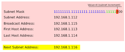
The
value of the lowest bit in the network mask is going to be our increment
used to calculate the next available subnet address. With /26 the increment value is 64 (pic. 16).
So, if we add the increment to the last byte, we get the number of our next available subnet address:
192.168.1.0 + 64 = 192.168.1.64.
From there, this next subnet address (value) - 1 is the broadcast of our current subnet:
192.168.1.64 - 1 = 192.168.1.63 (current broadcast address)
Current subnet value + 1 = the first host address:
192.168.1.0 + 1 = 192.168.1.1 (first host address of current subnet)
Current broadcast address - 1 = the last host's address:
192.168.1.63 - 1 = 192.168.1.62 (last host address of current subnet).
Look at the below pictures which illustrate this method.
Pic. 16 - Subnet 1 - IP addresses

Pic. 17 - Subnet 2 - IP addresses

Pic. 18 - Subnet 3 - IP addresses

Pic. 19 - Subnet 4 - IP addresses

Pic. 20 - Subnet 5 - IP addresses

Now,
we're ready to start talking about routing. In my next post, I will
talk about a router, its functions,and basic operation. From there,
we'll start exploring routing protocols.
Subscribe to:
Posts (Atom)